Container handling
Guides, sensors, pucks, screws, stars or indexing devices may be needed according to container shape and stability.
View detailsAn automatic three-head dosing platform for applications where containers are indexed beneath dedicated auger heads and transferred to downstream closing, labelling or inspection equipment.
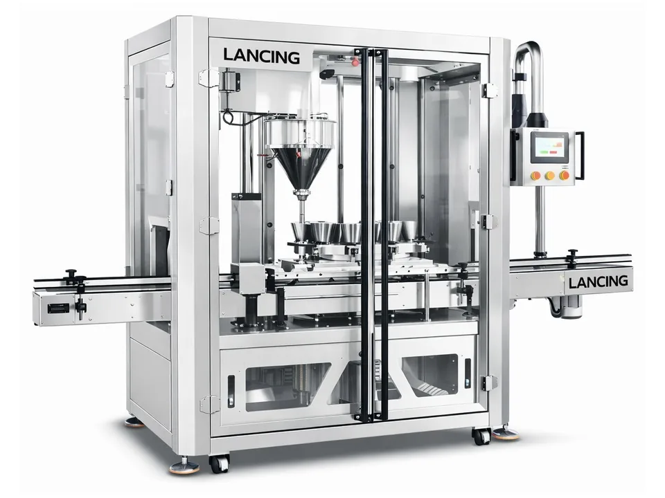
The Lancing LU-FM4A is an automatic three-head servo auger filler for powder dosing into indexed bottles or other approved rigid containers. Three independently driven auger stations allow multiple containers to be filled during each indexed cycle, reducing the cycle demand on any one head.
The standard reference range is 50 g to 300 g, but the production configuration is engineered around the approved powder, target dose, container opening and line sequence. Custom screws, filling tubes, nozzles and container-location parts are therefore part of application engineering rather than generic catalogue choices.
Final construction and line performance are confirmed after product, container and downstream-equipment approval.
| Specification | Reference model data | Application note |
|---|---|---|
| Machine format | Automatic three-head servo auger powder filler | Containers are indexed beneath the filling heads |
| Number of filling heads | 3 | Independent servo control supports coordinated multi-container dosing |
| Published fill range | 50–300 g | Dosing parts are configured for the approved powder and target |
| Filling nozzle | Custom diameter and anti-spill geometry | Bottle neck, powder flow and fill height determine the design |
| Reference line performance | Approximately 25–35 bottles per minute | Final sustained rate depends on trials and the complete line |
| Electrical supply | 400 V, 3-phase, 50 Hz; base machine approximately 6 kW | Final site supply and connected load require confirmation |
| Approximate machine size | 2,800 × 1,050 × 2,300 mm | Allow access for guarding, hoppers, maintenance and conveyors |
| Approximate weight | 600 kg net / 905 kg packed | Final execution and shipping arrangement can vary |
| Controls | Industrial PLC and colour HMI with recipes, counters, alarms and manual controls | Exact approved component platform may vary with the final build |
The filler must be engineered as part of the container and downstream process rather than as an isolated dosing head.
| Stage | Machine or line action | What must be proven |
|---|---|---|
| 1. Container infeed | Approved bottles are presented with controlled spacing and orientation | Container stability and upstream supply |
| 2. Indexing | Sensors and locating parts position containers beneath the heads | No-bottle/no-fill logic and repeatable nozzle alignment |
| 3. Filling | Three servo augers dispense the programmed doses | Powder refill, agitation, cut-off and head-to-head consistency |
| 4. Release | Filled containers leave the dosing station | Settling, rim cleanliness and stable transfer |
| 5. Downstream process | Containers continue to capping, sealing, labelling, coding or inspection | Line speed, interlocks, accumulation and reject handling |
Guides, sensors, pucks, screws, stars or indexing devices may be needed according to container shape and stability.
View detailsCap sorting, capping, sealing and label application must be matched to the filled pack and agreed line rate.
View detailsManual samples, inline checkweighing or feedback can be specified with agreed correction and reject rules.
View detailsA useful FAT uses production-intent materials and agreed acceptance criteria rather than an unrepresentative dry cycle.
| Input | Required detail |
|---|---|
| Powder | Representative normal and challenging batches plus relevant product or safety data |
| Containers | Sufficient approved bottles, including dimensional tolerances and least-stable examples |
| Target fill | Set point, tolerance, sampling plan and action for out-of-limit results |
| Downstream parts | Caps, labels, film, code layout and any inspection criteria that affect transfer |
| Line target | Required sustained finished-pack rate, shift pattern and expected product-change frequency |
| Acceptance method | Test duration, startup and refill conditions, data recording and deviation closure |
No. Three heads add dosing capacity, but the sustained finished-line rate also depends on container indexing, product refill, fill time, settling, capping, labelling, inspection and accumulation.
No. Nozzle diameter, profile and insertion depend on bottle opening, shoulders, fill height and powder behaviour. Approved containers and tolerance samples are required for tooling design.
The FAT and production control plan should identify each head, record individual samples and confirm head-to-head behaviour across starts, stops, refills and normal production variation.
Yes, the filler can be integrated with approved cap feeding, capping, labelling, coding and inspection equipment, subject to a coordinated layout, controls and performance review.
No. It is a reference integrated-line basis. The final rate must be established with the actual powder, bottle, tooling, acceptance criteria and complete line during trials and FAT.
Specification basis: Lancing technical specification and quotation records reviewed 20 August 2026. Values shown are reference machine data, not a guarantee for every powder, dose or pack. Final construction, tooling, utilities, output and fill performance are confirmed after product, pack and application approval.
Representative samples should be used to verify bulk density, flow, dust, aeration, bridging, cut-off, pack clearance and the agreed checking method before final specification.
Review the wider automatic filling route, indexing choices and downstream line planning.
View detailsPlan the feeder, filler, closing, coding, inspection and accumulation interfaces.
View detailsUse the verified model hub to compare pack handling, dose envelope and automation level.
View detailsInclude representative product and pack samples, required fill range, expected batch size, target output, available space and any feeding, sealing, capping, coding or checking requirements.